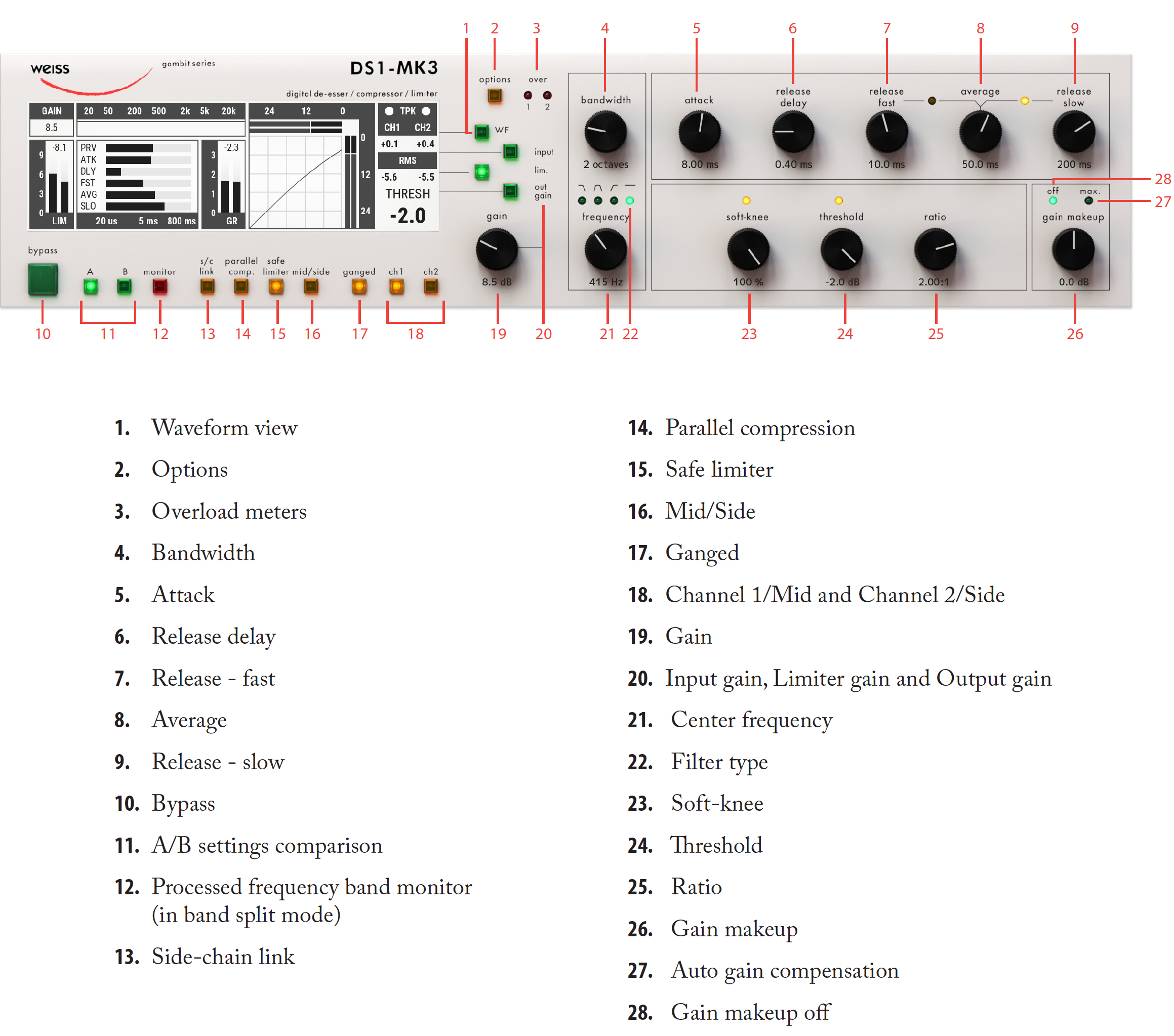
This two channel digital De-esser / Compressor/ Limiter features linear-phase crossover filters covering the whole audio band. The controls for the two channels can be ganged or unganged (useful for M/S compression). Similarly, sidechain linking can be turned off. Double-precision up- and down-sampling units within the DS1-MK3 result in high transparency for absolutely clean sound. The non-linear segment can be adjusted from 1000:1 to 1:5, allowing every kind of dynamic processing, from limiting to upward expansion (for over-compressed signals). Put back a little dynamics into that ultra-finalized mix! An additional safety-limiter Type 1 and Type 2 will allow the most transparent sound for mastering and mixing applications.
Update from DS1-MK3 (v3.0) to DS1-MK3 plug-in
- New limiter Types added (Type 1 and Type 2, see description in the Limiter section)
- Processing resolution has been increased to 32 bit 192 khz (40 bit internal resolution)
- Added Waveform Display view for real-time gain reduction monitoring
- Options dialogs have been redesigned for better ergonomics in computer environment
- Preset management can now be done in the DAW or a dedicated Preset Collection tool
- Screen is now interactive. Users can click and change on various screen elements and settings (see the detailed description in Screen section)
- Original Data/Gain knob now performs only Gain change function
There are three types of limiters available in DS1-MK3 plug-in:
- Original Safe limiter from DS1-MK3 hardware
- New generation Weiss brick-wall Limiter Type 1
- New generation Weiss brick-wall Limiter Type 2 (True Peak)
Limiters Type 1 and Type 2 are designed to provide the most transparent sound for mastering applications performing at high RMS levels.
TIP: Use Type 1 for highest RMS values and Type 2 when True Peak limiting in needed.

Dithering: Sets dithering to 16, 20 and 24 bits
Limiter: Option Allows to choose the limiter types. (see Limiter section)
RMS Detect: In the DS1-MK3 the peak measurement is supplemented with an RMS measurement with variable averaging time. The left endstop of this parameter switches the detection to Peak mode (default one).
Copy option allows to copy channels and settings from A to B, B to A, and channel settings from Channel 1 to Channel 2 and vice versa.

TIP: you may copy or switch the settings from the bottom panel of plug-in as well.
Sidechain: Sets the internal or external sidechain.
Limiter meter range: Changes the range of the meter.

TIP: It is possible to change the meters range from the main screen by clicking and dragging the meters.
Compressor meter range: Changes the range of the meter.
Peak Meter: Changes the meter type from onsample peak meter to True Peak (intersample) meter.
Knee Range: Changes the visible range of the Knee on the main screen.
Meter Text parameter: Changes the peak meter from Peak to Hold. In Peak mode the meters read the instant values thus change values faster, while in Hold mode the meters update the peaks slower.
Reset hold: Resets the meter to the current peak value.
Peak reset: Sets the automatic peak reset option to ON and FF

Set # of Overs: Sets the number on consecutive on-sample overloads to detect and report overloads. By default the number is set to 3.
Following is a detailed description of all parameters that can be adjusted in the compressor stage. Guidelines are given for settings (see also the factory presets), but optimal settings are usually programme dependent, so experimenting and listening is inevitable for satisfying results. Graphic 1 shows schematic and parameters of the DS1-MK3 compressor stage:
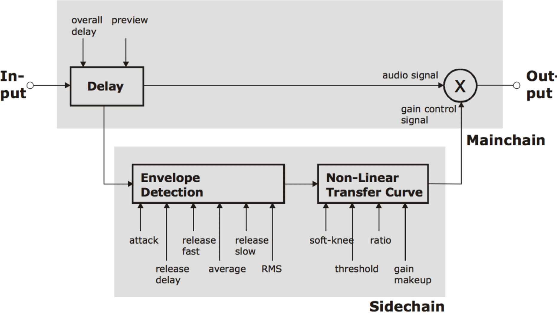
Graphic 1: Compressor schematic.
Attack and Preview: The longer the attack time, the more will the leading edge of fast transients pass by the gain reduction circuit unaltered (as in Graphic 2 during attack phase). Very fast attack time settings such as 20µs, i.e. one sample period, do catch every transient, but may distort low frequencies. To utilise longer attack times and still catch fast transients, use preview.
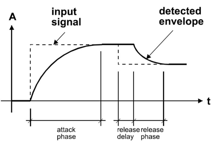
Graphic 2: Envelope parameters.
Release and Average: The input signal is monitored with two different methods: peak am-plitude and RMS value. The peak amplitude is the programme por-tion we don't perceive as very loud, however which can easily cause overloads. The RMS value of the programme material we perceive as loudness. Its variations contrib-ute most to the dynamic range of the audio. The sidechain processor compares the two measurements it obtained from the peaks and the RMS. The ratio between the two determines which time constant would be the appropriate release, e.g. after short duration peak the faster release will be applied during the release phase. The time period over which the RMS value of the programme material is averaged is set by the "average" parameter. The effect of the average parameter can best be studied on the gain reduction meter. Fast "average" settings will cause most of the gain reduction meter to move very fast (depending on the "release fast" setting) , slower settings will just have the top part of the gain reduc-tion move fast, with the bottom part depending on the "release slow" setting.
Release Delay: Normally the release phase begins immediately after the programme material has fallen in level. The release delay determines how long the DS1-MK3 holds the current level before entering release (see Graphic 2). The resulting dynamic characteristic is very smooth and avoids otherwise typical 'pumping' effects. The ideal setting is programme dependent and ex-perimentation may be necessary to achieve the best combination of all dynamic parameters.
Non-Linear Transfer Curve: This part of the sidechain is responsible for the actual gain reduction calculations. The detected signal envelope is compared with the transfer curve, the gain control signal (see Graphic 1) is then ad-justed accordingly if the envelope overshoots the transfer curve.
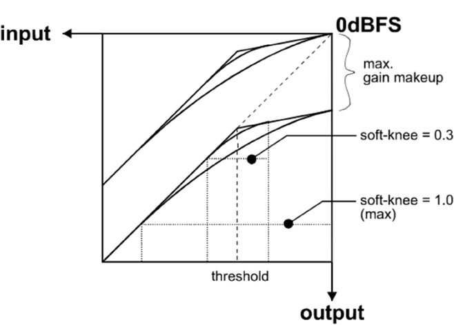
Graphic 3: Envelope parameters.
Threshold: Sets the level which the envelope signal has to reach before gain reduction is applied. Ratio: Sets the slope of the segment above the threshold.
Ratio: The Ratio can be adjusted for compression or expansion, depend-ing on the requirement. For full band expansion (e.g. to reintroduce dynamics into an over-compressed signal), one will usually work with the gain makeup set to maximum. This means that a 0.0dB input will be passed through without gain, signals below the threshold will be reduced with a constant gain (depending on threshold and ratio setting, can be read from the display when touching the gain makeup controller), and signals between the threshold and 0.0dBFS get expanded. For full band expansion, one will typically have quite high thresholds (-1dB ... – 4dB), because of the result-ing overall gain. The expander can also be used in frequency selective mode, for example to repair the effect of a misused multi-band compressor – for this purpose, the gain makeup can be set higher than the calculated maximum setting, to compensate for the overall gain that the expander causes. This can potentially cause overs (for loud signals in the expanded band), it is therefore good practice to engage the safety limiter.
Soft-knee: Determines how much the knee is rounded. The maximum setting (1.0) chooses a curve that reaches from 0dBFS down to twice the threshold value. This implies that if soft-knee is engaged the signal is already affected even if its envelope lies below the threshold.
Gain makeup: Moves the whole transfer curve up or down. In de-essing mode the gain makeup is usually set between the minimum (- 10dB gain) and "off" (0dB gain) to actually attenu-ate the processed signal, while in compressor (full band) mode the transfer curve usually gets to lie anywhere between "off" and "max", according to the amount of loud-ness correction one wants to apply. Once "max." is on, the transfer curve is attached to 0dBFS for maximum possible gain. "max" is engaged as soon as the curve reach-es 0dBFS by manipulating any combination of the above parame-ters, or by selecting "max" from the gain makeup menu. This mode can be exited by manually reducing the gain makeup or by selecting "off" from the gain makeup menu.
Band Selective Mode vs. Full Range Mode: The DS1-MK3 can be used in conjunction with a frequency crossover (band selective mode) or straight (full range mode).
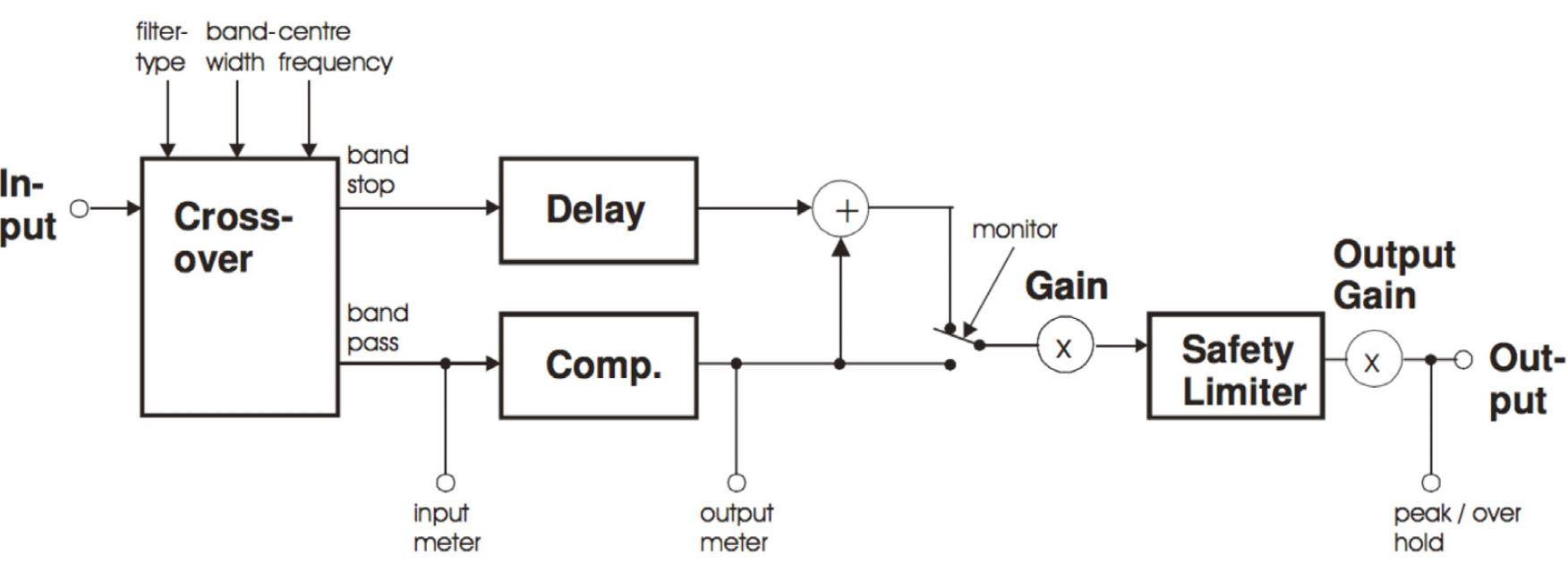
Graphic 4: Band selective mode.

Graphic 5: Full range mode.
Band Selective Mode: In this mode, a frequency crossover is put into the signal path, splitting it up into two or three bands, de-pending on the filter type setting.
One of the bands is com-pressed, the other is delayed by the same amount used as "delay" in the compressor stage. This mode is completely transparent if no gain reduction is applied.
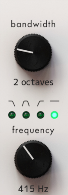
Filter Type selects the available filter types: Low Pass, Band Pass and High Pass.
Frequency changes the center frequency of the selected filter.
Bandwidth selects the width of the selected frequency band.
Parallel Compressor: The DS1-MK3 can be used in parallel compression mode, where the compressed signal is added to the straight signal.
Parallel Full Band Compression: As can be seen in Graphic 6, the input signal and the compressed signal are summed. The gain make-up value can be used to control the amount of compressed signal. The pre-limiter gain can be used to scale the mix before limiting.
Parallel Band Selective Compression: To add even more subtle compression, the compressed signal can be filtered before compression. Using the monitor function, one can listen to the filtered signal for optimal crossover setup (See Graphic 7).
Read this quote from Bob Katz: “You want a patch that compresses without stomping on the attacks at all, preserves transients but gives you great inner detail? ... You have one control, one control only, and that is the output level of the compressor [gain makeup], the ‘sidechain’.

Graphic 6: Parallel band full compression.

Graphic 7: Parallel band selective compression.
You can bring out inner details without losing breathing, and hardly affecting the upper dynamics at all. Works great. Not just great, absolutely fantastically. Fattens bass instruments without causing breathing or pumping. You name it, it works very well. Variations: Use it by split band [i.e. parallel] compression, so that (for example) high frequency inner details at low levels are enhanced”. This last paragraph refers to parallel band selective com-pression (crossover in highpass mode).
Starting point for parallel compression: Set the thresh-old for -50 dBFS, ratio to 2.5:1, attack to the fastest (microseconds), release to mid, around 250-300 ms (adjust to taste if you hear breathing or pumping). The makeup gain governs the amount of compression.
Graphic 7 shows the effect of Parallel Compression on the transfer curve (upper graph). Lower levels are raised while higher levels are not much affected.
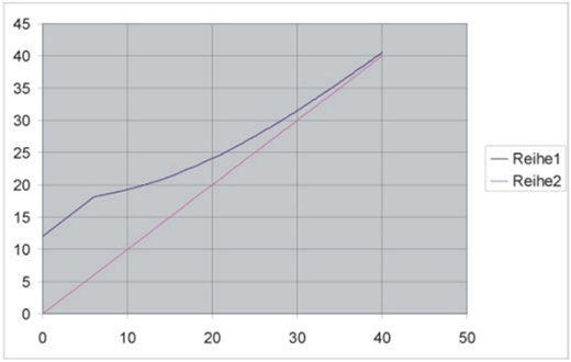
Graphic 7.
The DS1-MK3 allows for independent parameter settings in channels 1 and 2. If the ganged key is lit, both channels operate with the same parameter set. If the ganged key is not lit, the two channels can operate with different parameters. The CH1 and CH2, Mid/Side key assigns the knobs and the display to the appropriate channel.
Mid/Side Mode and Sidechain Link
The DS1-MK3 can be switched to Mid / Side mode. In M/S mode it usually is preferable to set the channels unganged and the sidechain unlinked.
Graphic 8 shows the block diagram of the DS1- MK3 when in M/S mode.
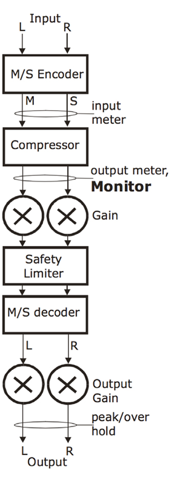
Graphic 8.
Monitor Key
In band selective mode pressing the “monitor” key al-lows you to listen directly to the processed band, ideal for zooming in on offending material and listening to the effect of the compressor stage. See above for the Monitor output position. The Monitor output works as follows: DS1-MK3 in ganged mode: The stereo signal is fed forward to the output. If the band selective mode is selected, only the active band is fed to the output. DS1-MK3 in unganged mode: The currently selected channel (CH1 or CH2 or M or S) is fed to both L and R outputs. This allows for instance to listen to the S signal only in order to adjust the compressor optimally.
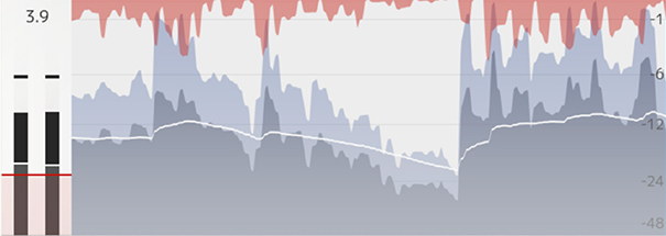
Waveform View
The Waveform view shows several meters in time: gain reduction, RMS and peak values.
The DS1-MK3 has easily accessible factory presets for a quick setup which can then be refined and adapted to the programme being processed. The first few factory presets we created at Weiss Engineering, then a whole bunch of presets created by Bob Katz follow. Bob’s presets come with a detailed on-screen description. Note that most of Bob’s presets need a threshold and/or a ratio dialed in in order to work. We invite users of the DS1-MK3 to supply their favourite presets for adding them to the list. To access the factory presets press the Presets at the bottom of the plug-in.
In the Setup menu you can enable “Bob Ludwig mode” that shows current parameter values under each knob.
A whole range of added control can be accessed with Extended Features. Please see the separate "Extended Features" manual for more information.
Paul Shyrinskykh –Product design and product management
Arvid Rosén – DSP and framework programming
Björn Rödseth, Kim Larsson – Framework programming
Niklas Odelholm – Graphic design
Ulf Ekelöf – 3D rendering
Maxus Widarson – Quality assurance
